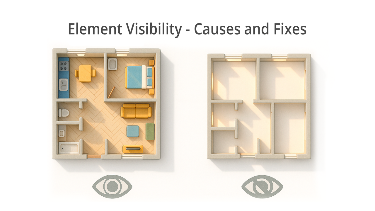
Why do elements disappear in Revit views?
📐 What is the View Range?
- In the Properties panel → Extent section
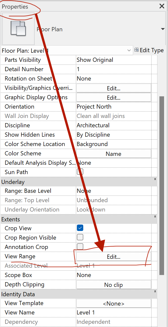
View Range parameter inside the Properties panel.
- Or in the View Template (if one is applied)
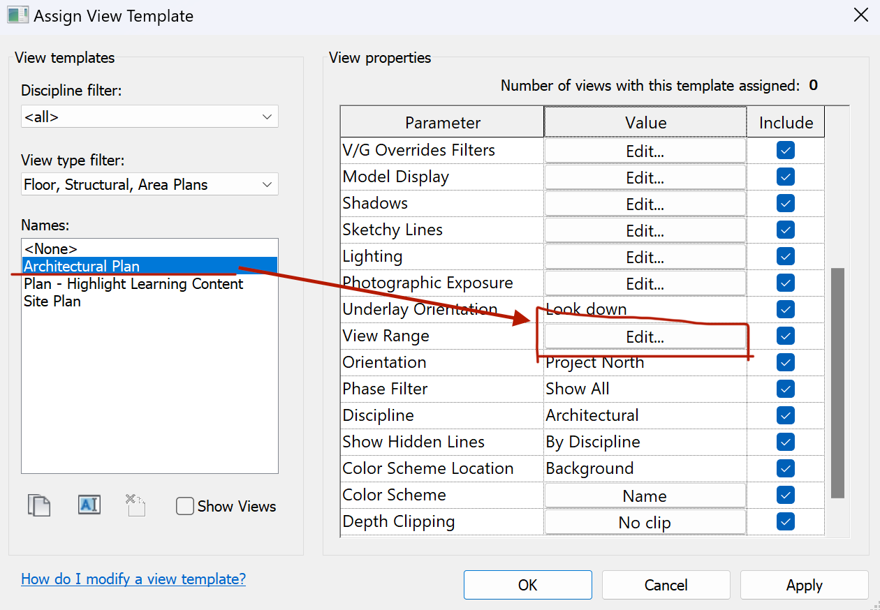
View Template overrides for View Range.
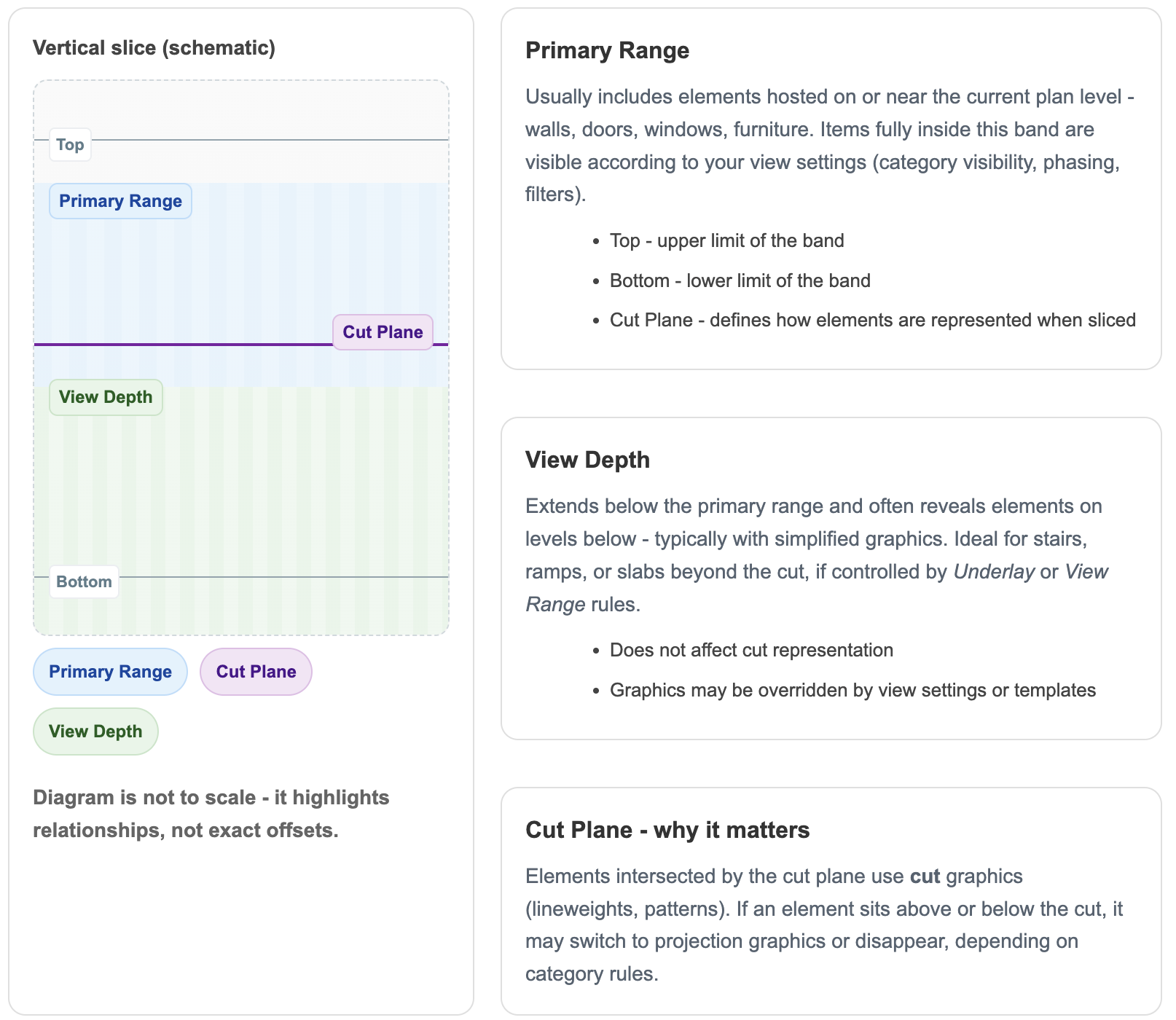
🧭 Two parts of the View Range

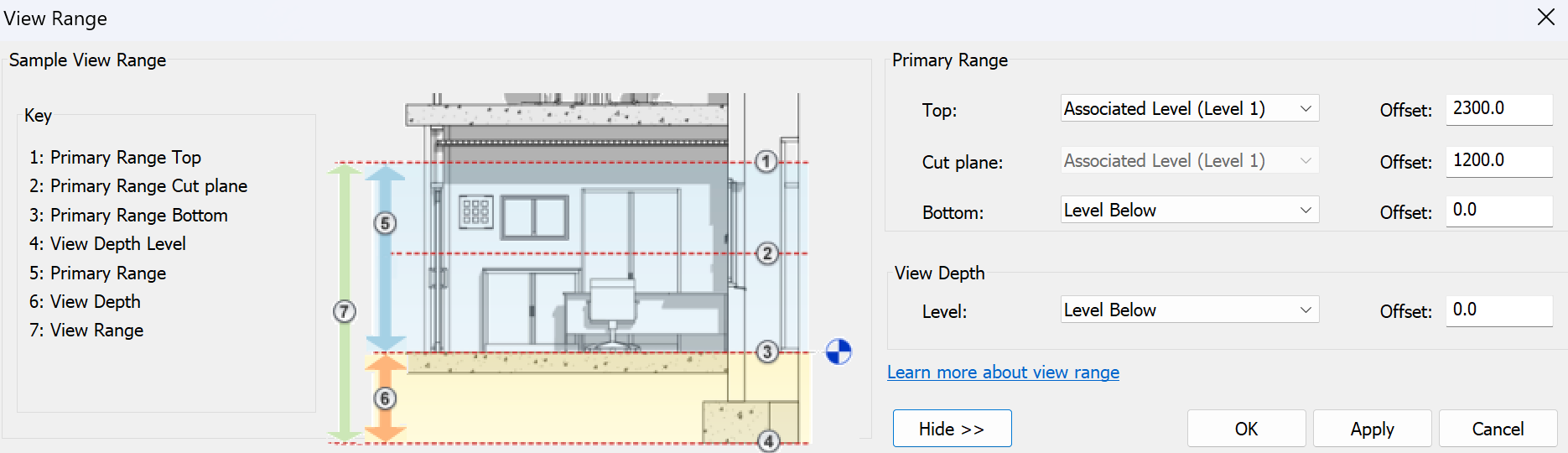
View Range – structure of Primary Range and View Depth.
📏 Key rules to remember
Revit is strict when it comes to logic. If your View Range settings don’t match the rules, elements simply won’t show up. Keep these rules in mind:
② The View Depth must always be below the primary range (Number 6)
🔔 Tip: If elements still don’t appear after adjusting the View Range, double-check whether a View Template is overriding your settings.
🗺️ Plan Region
The Plan Region tool is located under the View tab.
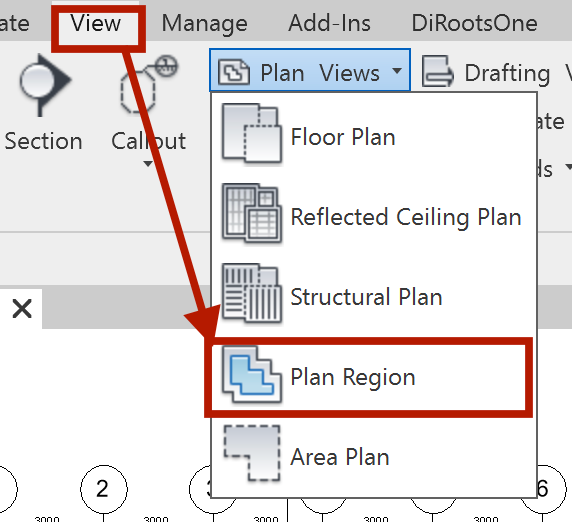
Plan Region tool on the View tab.
🎯 What it does

Example: revealing higher windows with a plan region
💡 Pro tip: You can place multiple plan regions in one view — each with its own custom view range.
✂️ Sections
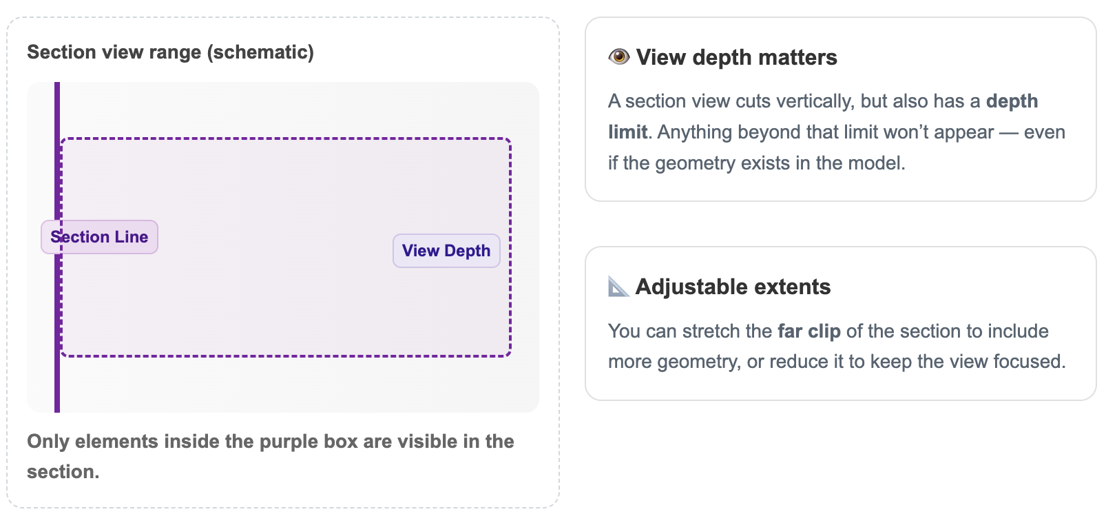
💡 Tip: Turn on the Section Box in 3D views to visually confirm what your section extents cover.
🎯 Far Clip Offset
Adjusting the Far Clip Offset to reveal missing geometry
📐 Section Boundaries
- Adjust the section extents using the boundary arrows on the floor plan
- Use the grips on the section box to stretch its limits
Stretching section boundaries to include missing elements
💡 Reminder: Both Far Clip Offset and Section Boundaries control visibility. Check them first before troubleshooting categories, filters, or worksets.
⚠️ Common Mistakes
The simplest mistake is also the most common: the section line doesn’t actually pass through the target element.
- ✅ Move the element closer to the section cut line.
- ✅ Adjust the section line so it passes through the geometry.
- ✅ Flip the section using the double-arrow button (⇆).
Flipping the section with the ⇆ button
🕵️ Hiding Elements in Revit
Example: hidden elements due to view settings
🖱️ 1. Manual Hiding
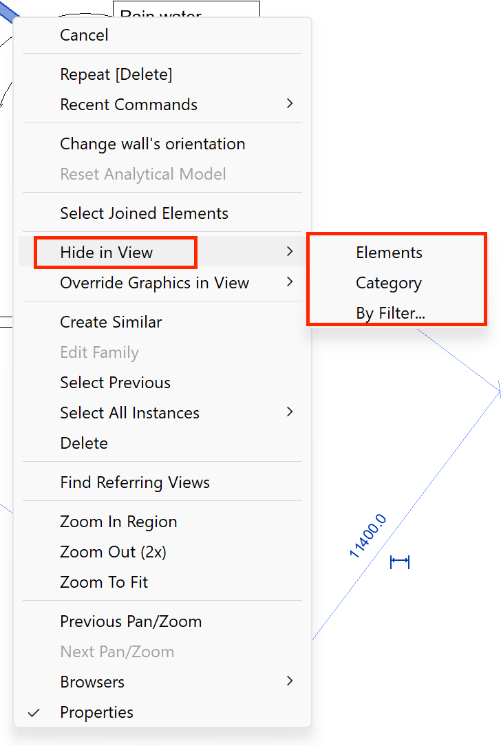
- Right-click → Hide in View → Elements The fastest way to hide a single object.
Context menu for hiding a single element.
Hiding an entire category in a view.

Applying a filter to control visibility.
Reveal Hidden Elements toggle on the ribbon.
Workflow for recovering hidden elements.
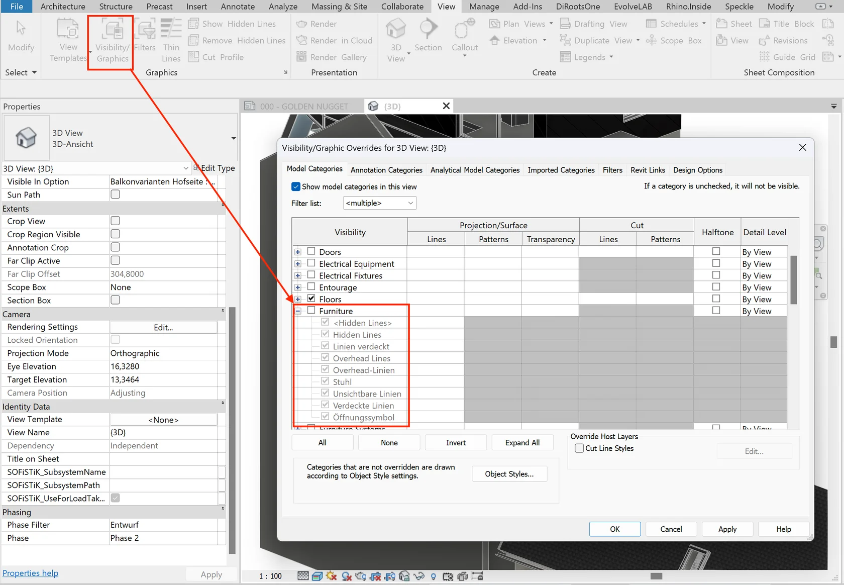
📊 2. Visibility/Graphics Overrides
- Turn categories and subcategories on/off
- Adjust fills, line weights, and halftones
- Manage linked or imported files (families, DWGs)
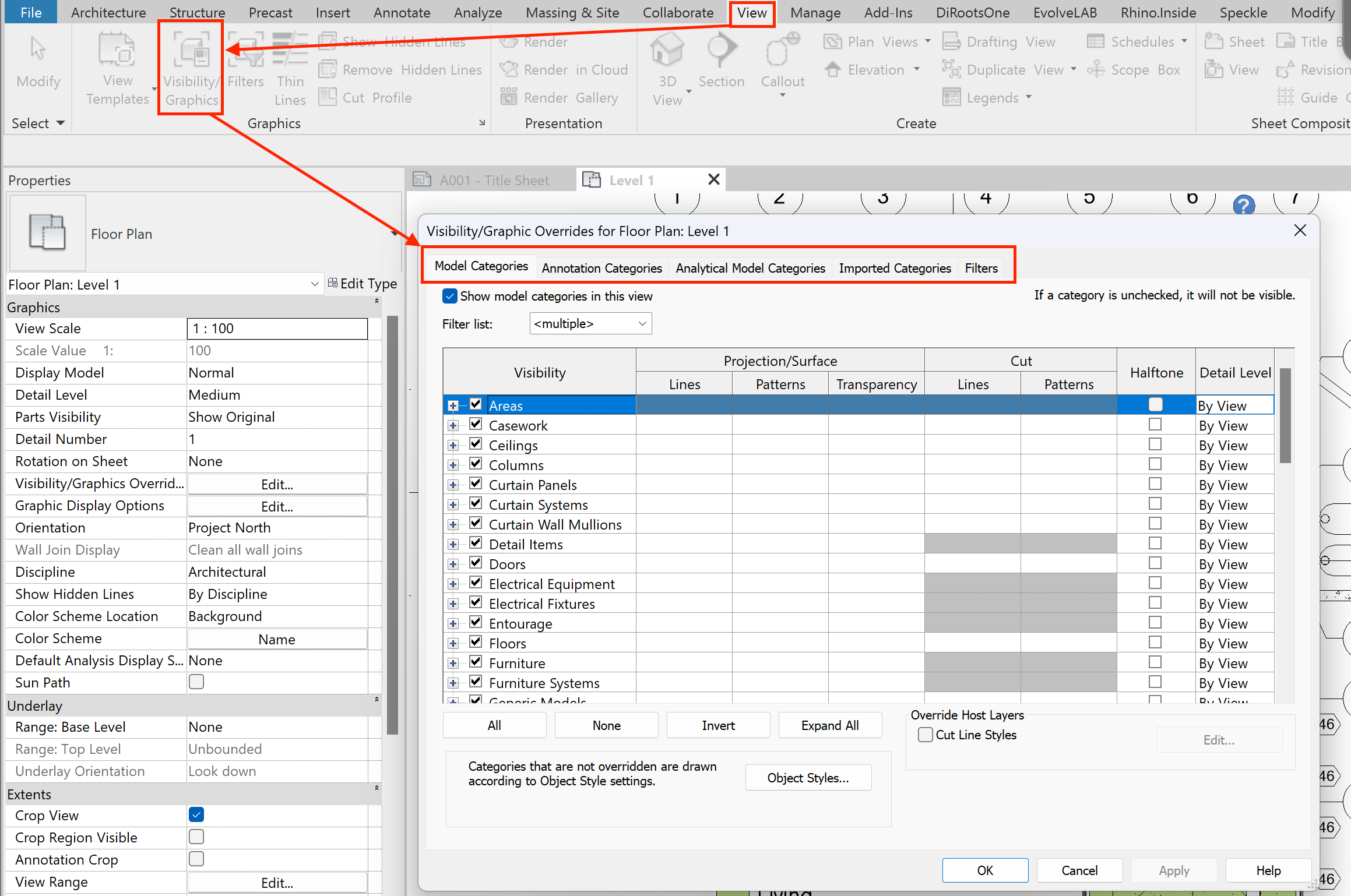
Visibility/Graphics Overrides dialog.
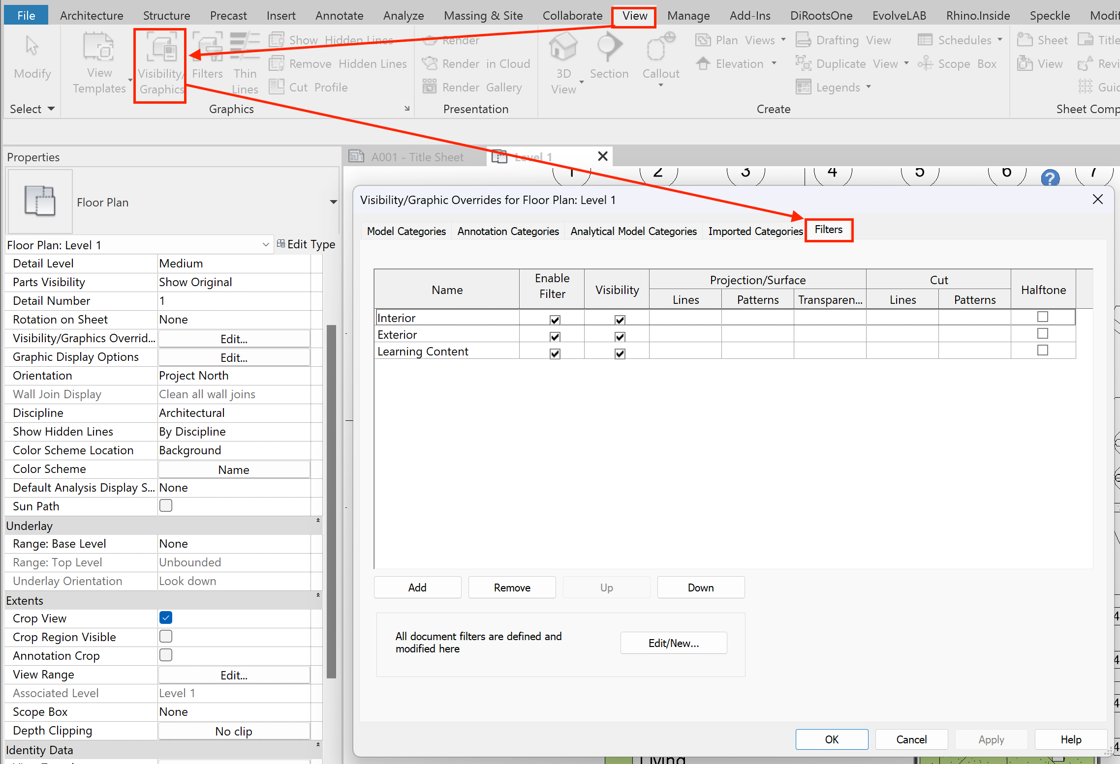
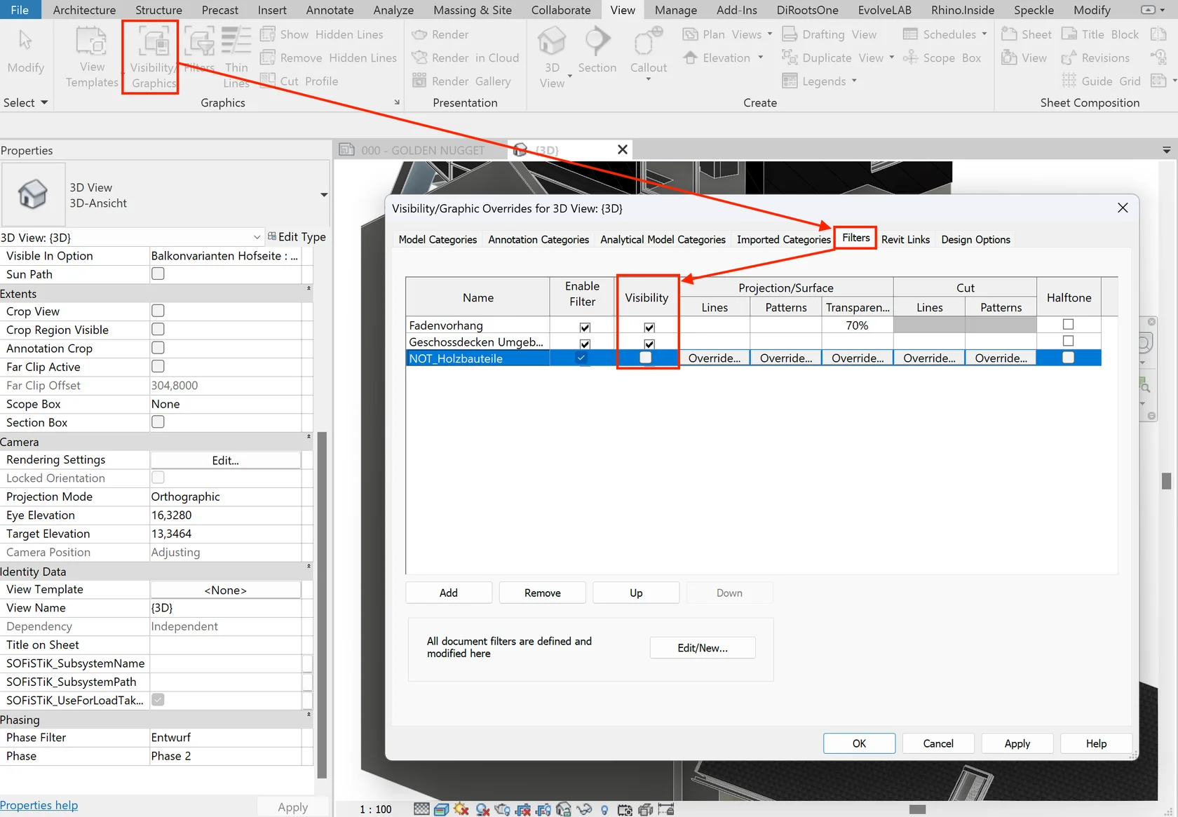
🧩 3. Filters
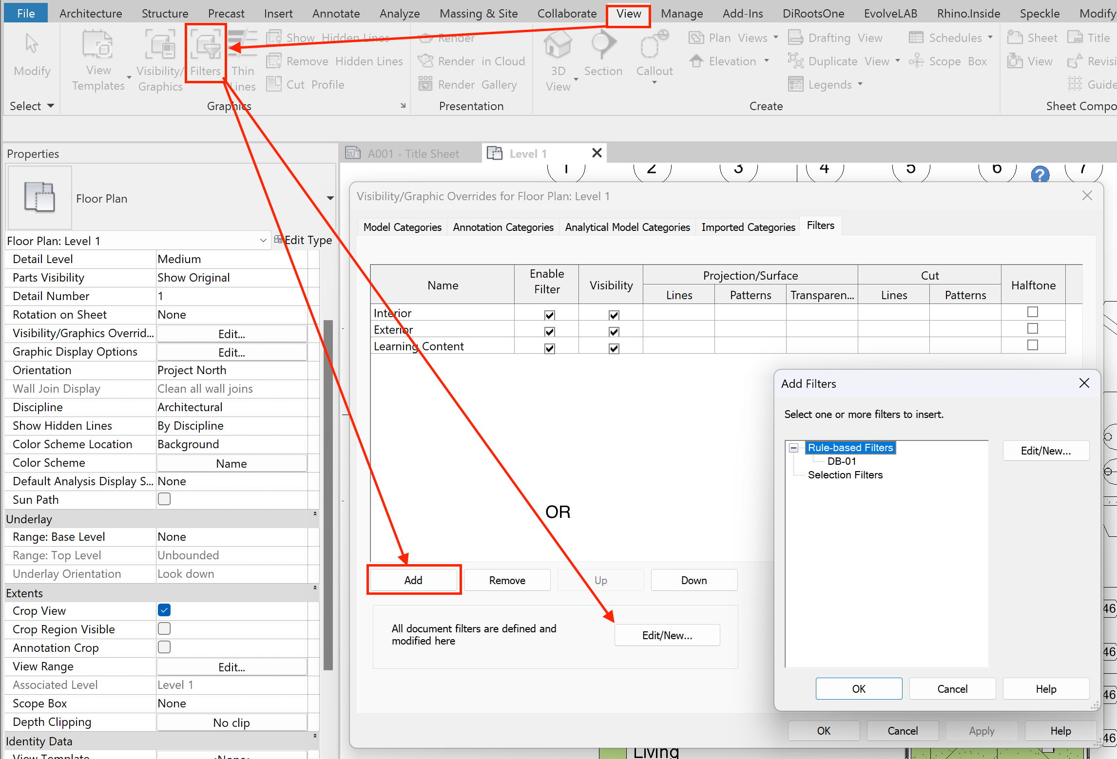
Visibility/Graphics → Filters list.
Filters rules setup dialog.
- Show or hide elements
- Override graphics with lines and patterns
- Select elements by rules
Workflow:
- Create or duplicate a filter
- Assign it to categories
- Define rules (equals, greater than, contains, etc.) with AND/OR operators
🗂️ 4. Worksets
⚠️ If “Use Global Setting” is checked, the behavior comes from the Workset Manager.
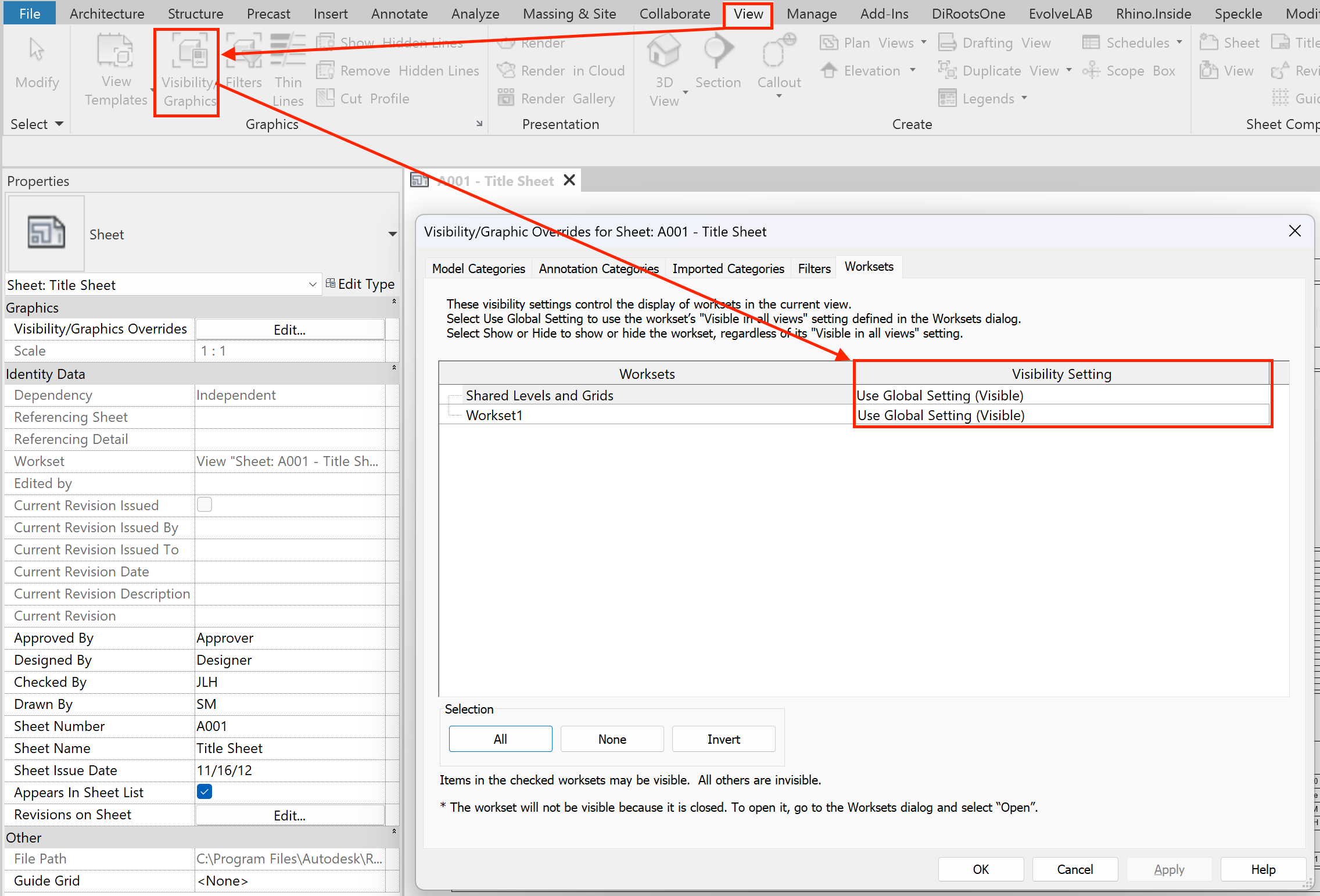
Workset visibility controls in a view.
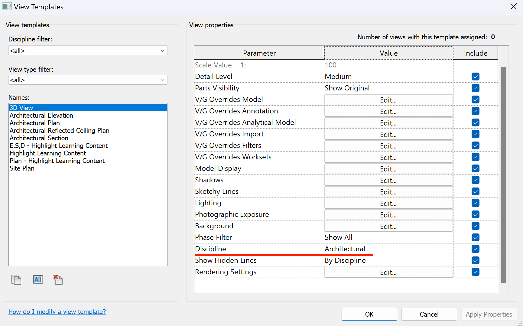
📝 5. View Templates
Demonstration of applying a view template.
Common mistake: not knowing which settings are locked by the template versus editable in the view.
- If a setting is controlled by the template → you can only edit it inside the template.
- If it’s not controlled by the template → you can adjust it directly in the view.
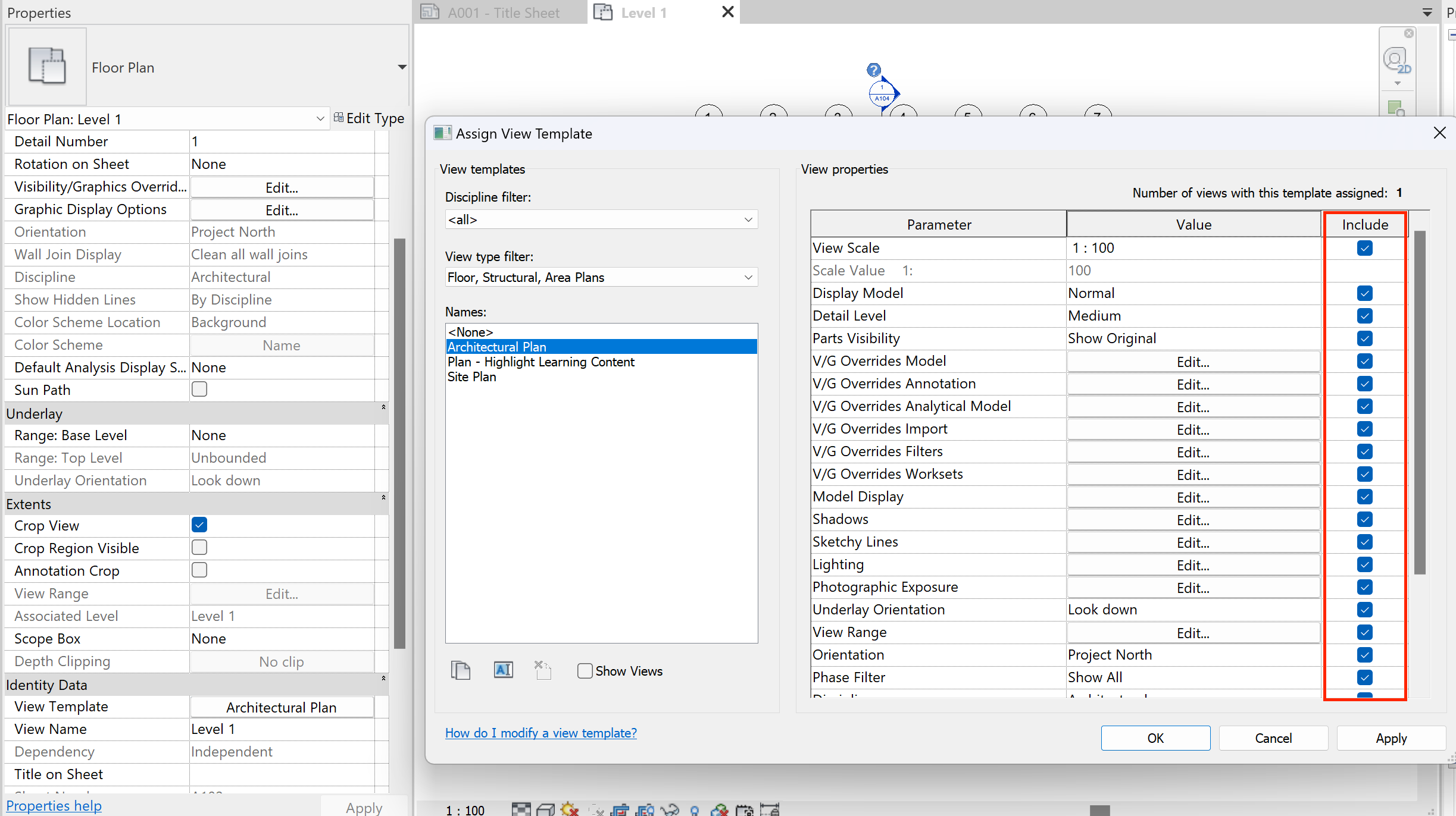
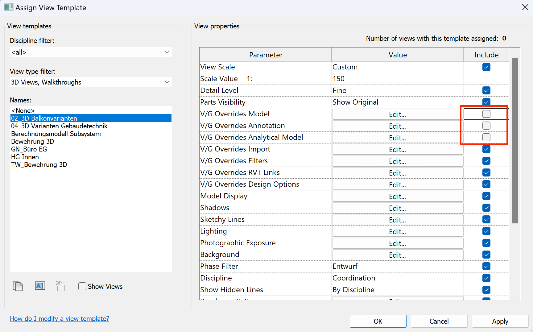
Parameters locked by the view template.
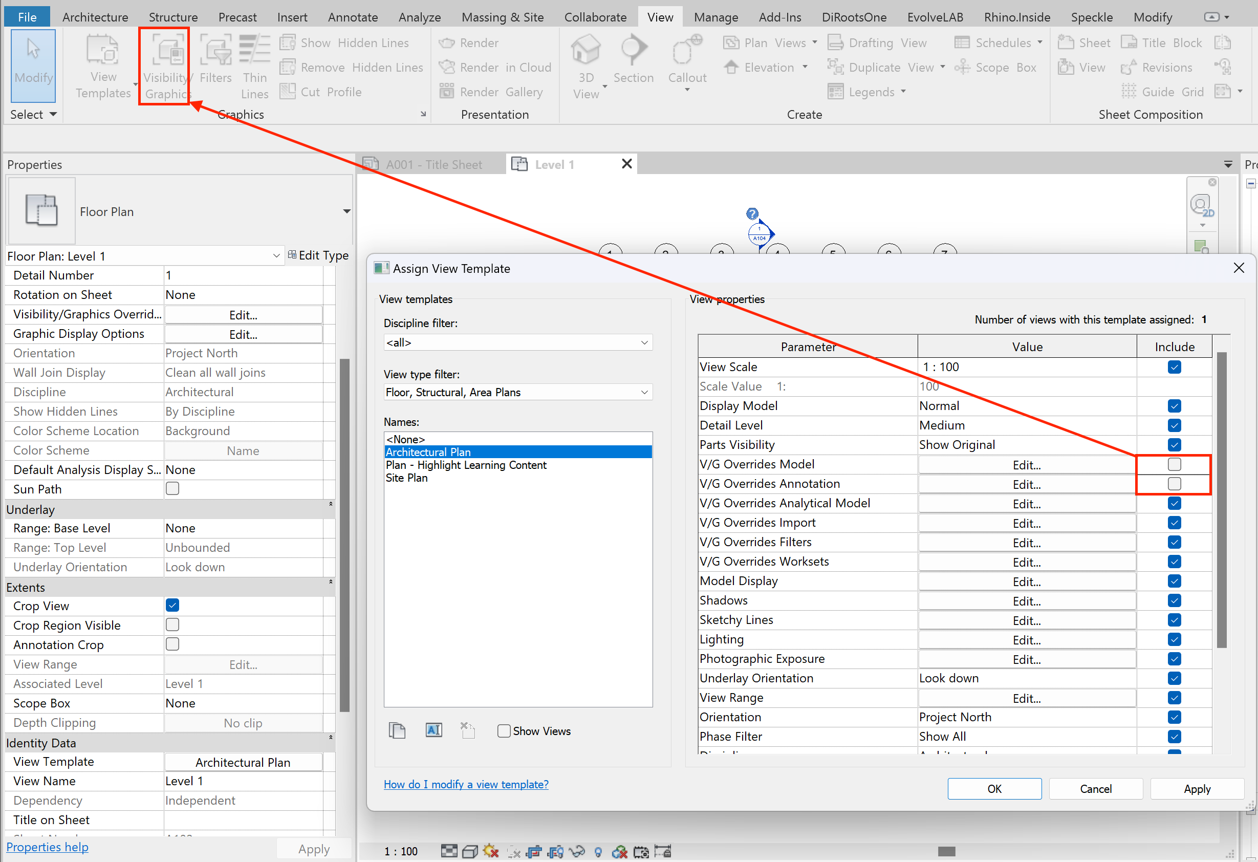
Parameters editable directly in the view.
⚙️ 6. Additional Settings
- Phasing — splits the model into phases (New, Existing, Demo). Can hide elements by phase.
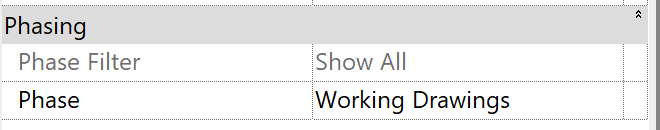
Phasing settings controlling element visibility.
- Discipline — adjusts graphics to match the discipline (Architecture, Structure, MEP).
Changing discipline to adjust graphics.
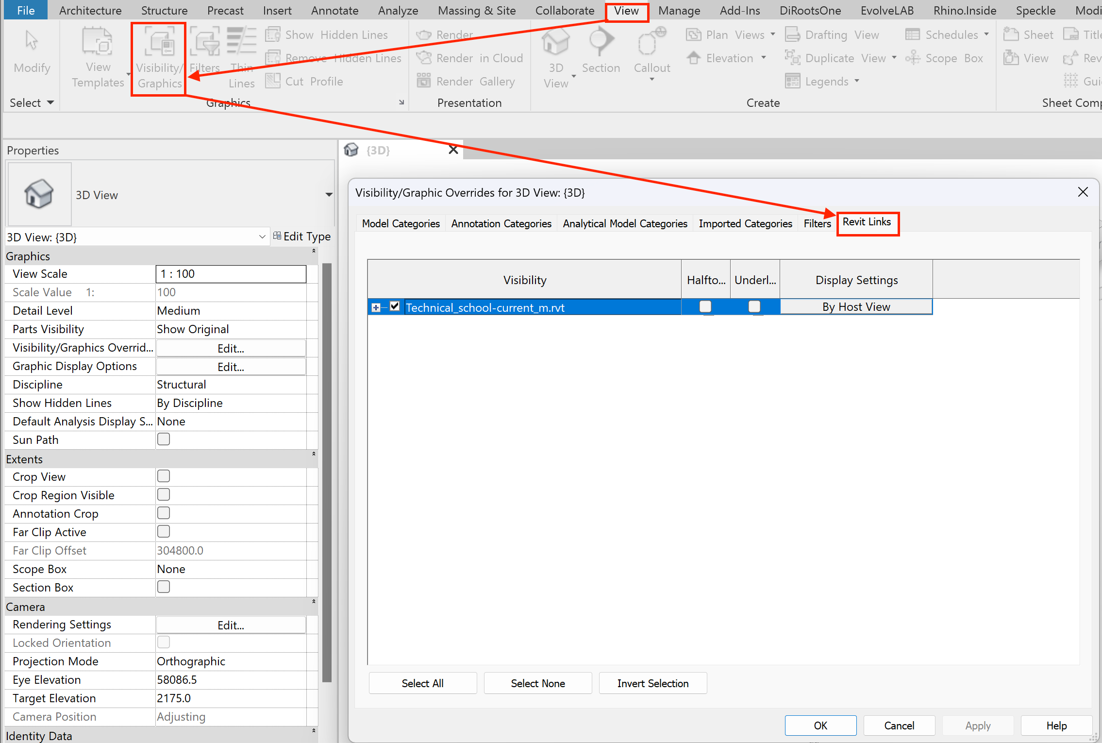
🔗 Linked Models in Revit
📌 Basic Method
Manual hiding of a linked model.
🗂️ Link Management Panel
- Left checkbox — toggles the entire link on/off
- “Plus” button — expands nested links or project codes
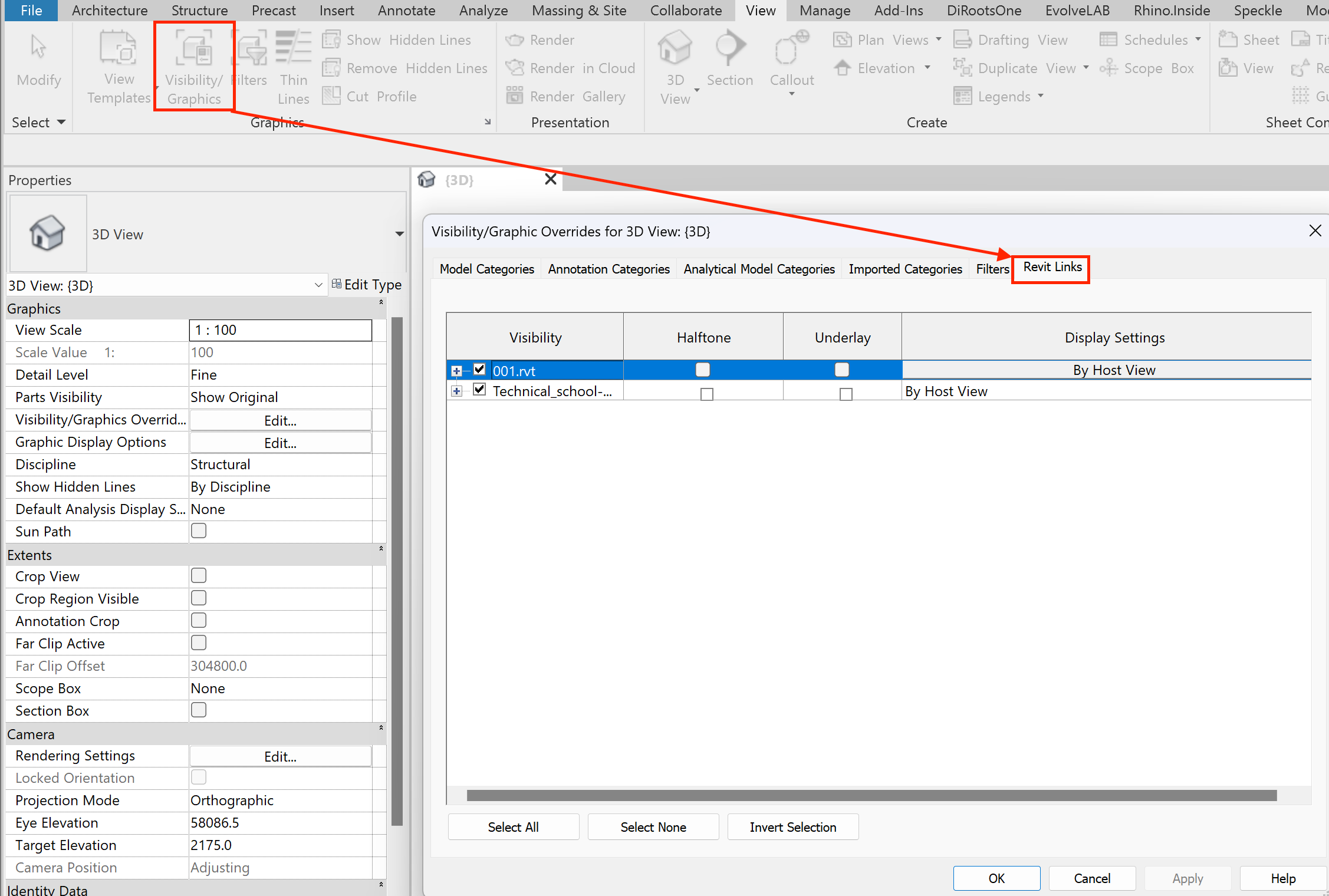
Visibility controls for each linked model.
Example of overriding a nested link.
🔍 From practice: most links are usually loaded as Overlay, so overriding nested links is rarely needed.
🎨 Quick Graphic Controls
- Halftone — fades the link by 50%
- Underlay — turns off hatching in the link
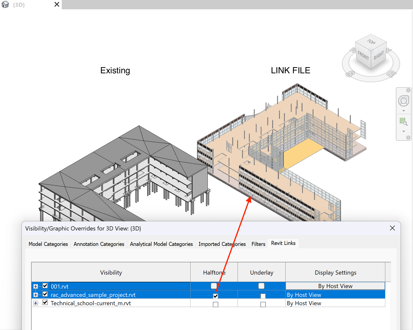
Halftone and underlay toggles for links.
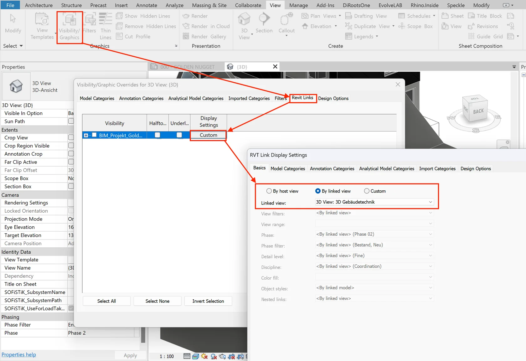
🎛️ Display Options
🔹 By Host View — inherits visibility from the main project view or template (locked, not editable).
🌀 Design Options in Revit
- Design Options — tool for creating multiple alternatives in one file without duplicating the model.
- Option — a specific alternative solution.
- Option Set — a group of options for one part of the project.
- Primary Option — the chosen solution that displays by default in views.
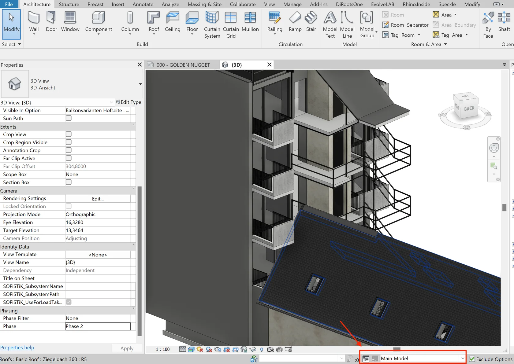
- Main Model — the base project with all common elements. Option sets are created inside it.
🪜 Step-by-Step Workflow
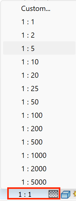
Use the button on the bottom toolbar.
② Create Option Sets and Options
Start with option sets, then add individual options inside them. Options can be renamed or duplicated.
- Elements in the Main Model appear grayed out when working in an option
- Elements in other options are invisible
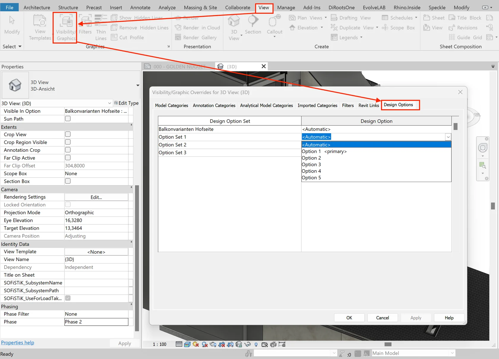
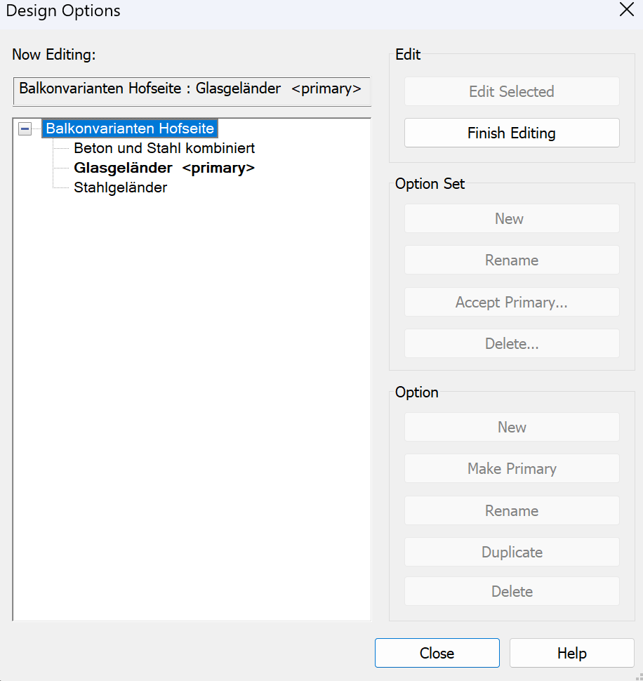
- Visibility can be adjusted in Visibility/Graphics → Design Options
- The <Automatic> setting shows the Primary Option
To transfer elements from the main model into an option:
- Select them
- Click “Add to Set” and choose the target option
- The elements will be removed from the main model
Alternatively: Ctrl+C → Modify → Paste.
- The Primary Option always displays in the main model
- Once the decision is made, click “Finish Editing”, then “Accept Primary”
- The set is deleted, and the primary option is merged into the main model
You can verify this in the Instance Properties of the element.
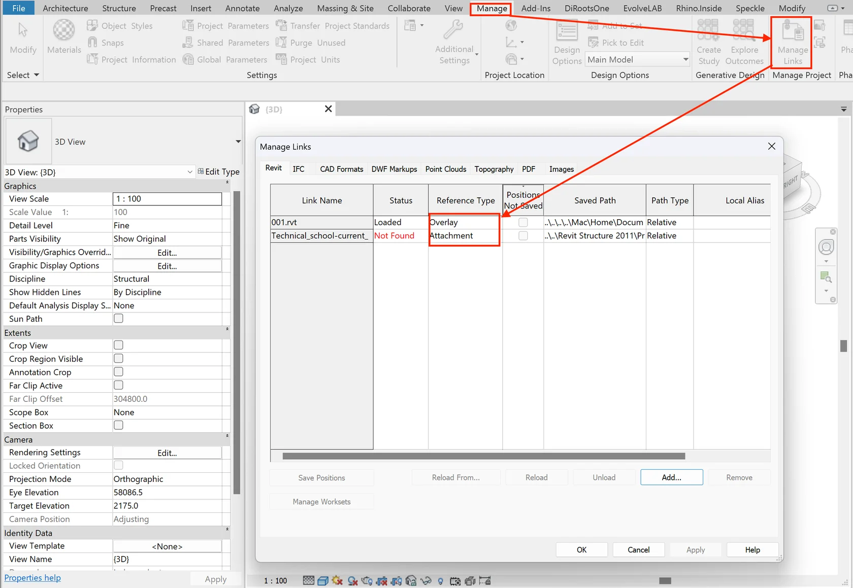
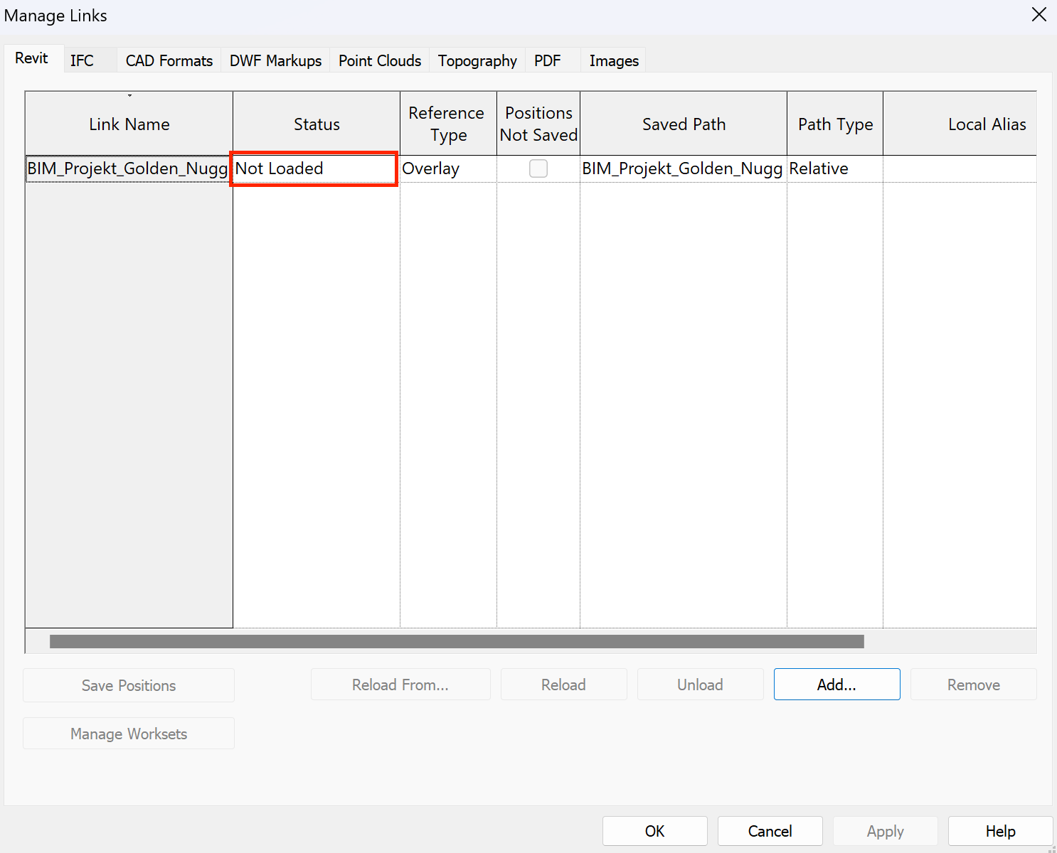
🔍 Common visibility issues with elements, annotations, and linked models in Revit
Possible reasons:
- The file is loaded but hidden
- The link is turned off in Manage Links
- The linked model is placed outside the visible area
✅ Open Manage Links and check if the model is loaded
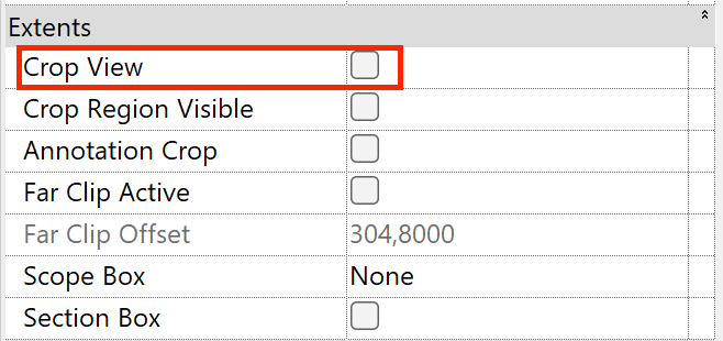
✅ Turn on Reveal Hidden Elements (💡)
✅ Switch to a 3D View or disable Crop Region
🚫 #2 Incorrect Visibility/Graphics Overrides
- Enable checkbox turned off in View Template
- Category/subcategory unchecked
- Multiple filters applied
- Incorrect Linked View assigned
- Custom visibility overrides hidden deep in menu
✅ Open the View Template and check Include
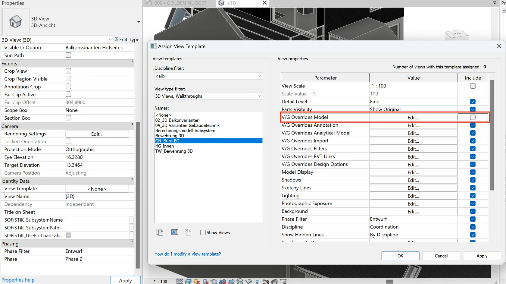
✅ Verify categories in Visibility/Graphics
✅ Review applied filters
✅ Double-check the assigned Linked View
🚫 #3 Workset elements are hidden
- Workset turned off in the current view
- Disabled in View Template
- Hidden via linked model overrides
✅ Review managers & settings one by one to enable workset
🚫 #4 Design option elements are hidden
- Only the Primary Option is visible by default
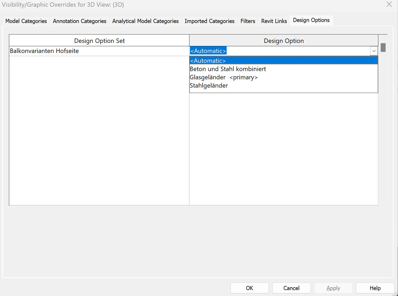
- A different option was selected in Overrides
✅ Select the required option in Design Options
✅ Adjust visibility for the option set
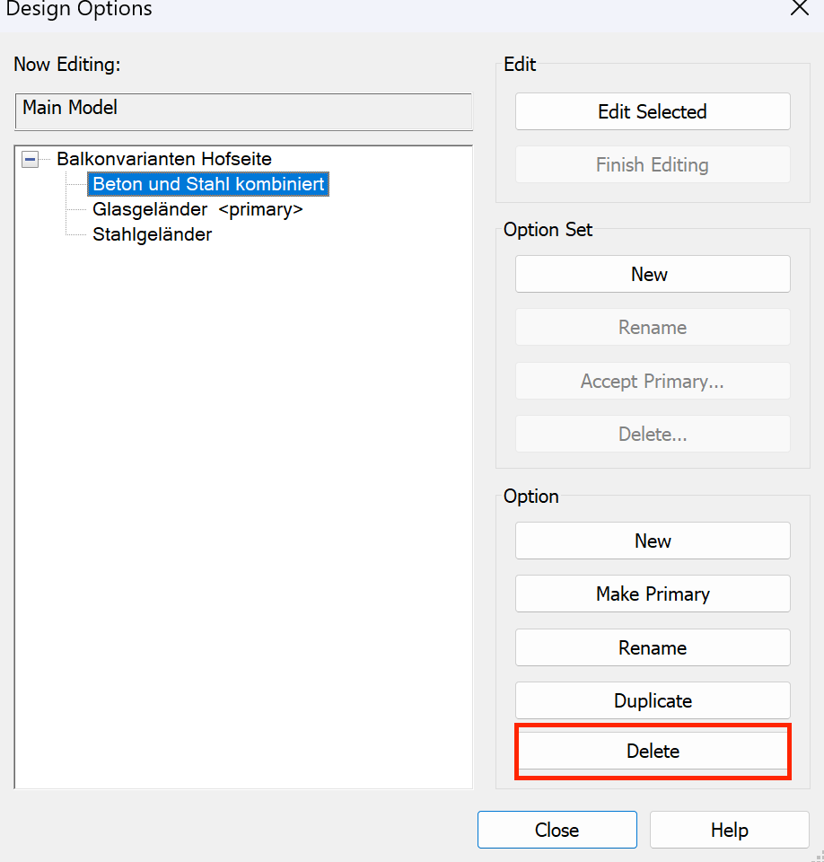
🚫 #5 Model elements cannot be selected
✅ Switch to the target Design Option & edit ✅ Or set as Primary & accept ✅ Or delete unused option
🚫 #6 Incorrect element count in Design Options
- Schedule linked to the wrong Design Option
- Alternative options exist & affect count
✅ Check schedule properties for the correct option ✅ Remove unnecessary design options
🚫 #7 Annotations disappeared
- Annotations hidden manually
- Category turned off
- Filtered out
- Confusion between View vs Template
- Incorrect Linked View settings
✅ Turn on Reveal Hidden Elements
✅ Check annotation categories
✅ Review filters
✅ Check View Template
✅ Configure correct Linked View (coords, range, level)
🚫 #8 Grid lines are not visible
- Grids don’t extend to the level
- Grids don’t reach the view range
- Workset with grids is off
✅ Extend grids to intersect level
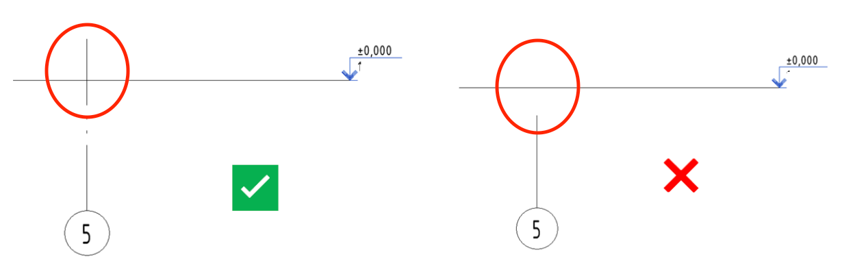
✅ Extend grids to cross-section/elevation range
✅ Enable workset 00-General levels and grids
🚫 #9 Family annotations display incorrectly
- Visibility tied to Detail Level
- Symbols visible only at certain View Scale
✅ Adjust View Scale or Detail Level